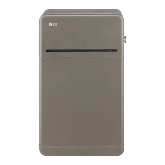
Table of Contents
Advertisement
Quick Links
16/04/2021
INSTALLATION MANUAL
Residential
Battery unit
Part 1
LG Electronics strongly advises users to exercise due care in following LGE's
product installation manual. A warranty claims are invalid if damage is
caused by human error, inconsistent with the installation manual.
MODEL
LG HBP10H
(BLGRESU10HP)
Read in conjunction with Part 2.
Advertisement
Table of Contents

Summary of Contents for LG HBP10H
- Page 1 INSTALLATION MANUAL Residential Battery unit Part 1 LG Electronics strongly advises users to exercise due care in following LGE’s product installation manual. A warranty claims are invalid if damage is caused by human error, inconsistent with the installation manual. MODEL...
-
Page 2: Table Of Contents
The information included in this manual is accurate at the time of publication. However, this manual is subject to change without prior notice. In addition, the illustrations in this manual are meant only to help explain system configuration concepts and installation instructions. -
Page 3: Safety
Do not dispose of the product with household waste The Product includes internal fault mechanisms designed to prevent failures and subsequent risk hazards. However, LG Electronics cannot guarantee safety performance of the Product is ever exposed to abuse, damage or negligence. -
Page 4: Warning Label
: Electrical license for battery installation required by the country or state Battery CE / RCM / IEC 62619 / UL1973 / • Repair the battery by disassembly is possible only at the LG Service Center or by Pack IEC62477-1... -
Page 5: Features
1. Short Circuit Current/Duration 2.3 Maintenance Short Circuit Current 1.106 kA BLG RESU10HP does not require maintenance during normal operation if properly installed Duration 0.97 ms per the installation manual. In the event of fault, contact the regional service center. 2.4 Packaging Specifications 2. -
Page 6: Basic Lifting Guide
3.1.2 Basic lifting guide 5. Pull out Battery Module B. Refer to below guide for lifting and carrying the Battery Control Unit and Battery Modules during installation. Handling position Handling position Handling position Handling position Handling position 6. Pull out Battery Module A. 7. -
Page 7: Clearance
* Fastener separation should observe It is required to wear the following safety gears when handling the battery pack. the regional building code. * Check “LG HBP10H Standing” on the middle side of Drill Template before drilling. 2. Place a spacer to the position marked on the Drill template. - Page 8 3. Remove the Drill template and fi x the 7. Remove bubble wrap from Battery Control Unit Standing bracket 1 on the wall. connectors of Battery Control Unit RESU Drill Temp Prime late and the warning label of Battery Modules. Standing bracket 1 Standing bracket_1 4.
- Page 9 10. Connect the power and sensor 14. Realign the Battery Control Unit. connectors on the right and left sides (2 each). Assemble the connectors until you hear a “Click”. After that, F r o lock the power connector by pressing F r o F r o F r o...
- Page 10 19. Re-attach the top cover. 23. Assemble the adapter or cap according to regional regulations. * Tighten the M5xL65 Flange Bolt Then insert the power and (4ea) with a torque of 5N·m. communication cables through the holes from outside of the pack. * Arrange the internal cable as required to avoid blocking the holes for external cables.
- Page 11 LGES recommends the use of at F r o least 8 fasteners for Wall Mounting Bracket Bottom and 2 fasteners for Wall Mounting Bracket Top. Label * Check “LG HBP10H Wall Mounting (Optional)” on the Wall middle side of Drill Template Battery Module B Rear before drilling.
- Page 12 9. Place the Battery Control Unit on 13. Remove one spacer by lifting one Battery Control Unit Battery Control Unit top of the spacers, and align with the side of the Battery Control Unit. After B Lift (just few mm) Battery Module.
- Page 13 17. Plate the Wall Mounting Bracket Top 21. Assemble the adapter or cap Support in right plate as shown in according to regional regulations. fi gure and fi x on Battery Control Unit Insert the RMD ethernet cable using three (3) M6 Flange Bolts through Hole #2 and connect the cable.
-
Page 14: Installation Process For Remote Monitoring Device (Rmd)
* Make sure the Front Cover is closed. Handle ※ If you don’t have your account, please visit LG ESS Battery website and make an account. https://www.lgessbattery.com/us (in case of North America) https://www.lgessbattery.com/au (in case of Australia) https://www.lgessbattery.com/eu (in case of all EU-countries in general) https://www.lgessbattery.com/de (in case of Germany) -
Page 15: Installation Via Rmd
3.2.1.3 User Registration 9. Select the “Owner” option. 10. Enter your ID and Password. 3.2.1.3.1 Visit https://resumonitor.lgensol.com 11. Click the “Sign In” button. 3.2.2 Installation via RMD Click the link on the RESU Monitor website to download the APK fi le of the ‘RESU Installer’ App. - Page 16 3.2.2.3 User Agreement 3.2.2.5 QR Code Scan The QR code scanning method is as follows. 1. Search the product which you will install. 2. Get the agreement of privacy policy for the customer. 3. If the customer agrees the privacy policy, have customer’s personal information. Select Prime: Fixed at 2 FLEX: Select from 2 to 4...
- Page 17 3.2.2.8 Server Connection and Battery Status Check 3.2.2.6.2 Wi-Fi Connection If you are using an ethernet connection and do not wish to use Wi-Fi, simply click the “Next” button. IoT Hub Connection String: Enter the unique string provided to you in order to access the Azure IoT Hub (cloud server).
-
Page 18: Cable Connections
3.3 Cable Connections 4. Section E: Battery power port a) Connect the ground wire to Terminal 2. b) Connect the negative line of the power cable to Terminal 3. c) Connect the positive line of the power cable to Terminal 1. ※...


